
News
News information-

Industry news
2025.10.09
The basic performance of connectors
The fundamental performance characteristics of connectors can be categorized into three main types: mechanical performance, electrical performance, and environmental performance. Another important mechanical property is the mechanical life of the connector. Mechanical life is essentially a durability indicator; in the Chinese national standard GB5095, it is referred to as "mechanical operation." One insertion and one withdrawal constitute a single cycle, and the evaluation criterion is whether the connector can still perform its intended connection function (e.g., maintaining specified contact resistance) after a prescribed number of mating cycles.1. Mechanical Performance – With regard to connection functionality, insertion and extraction force is a critical mechanical characteristic.Insertion and extraction forces consist of insertion force and withdrawal force (also called separation force), which have different requirements. Relevant standards specify maximum insertion force and minimum separation force. From a usability perspective, insertion force should be low (leading to designs such as Low Insertion Force—LIF—and Zero Insertion Force—ZIF connectors). However, if the separation force is too low, it may compromise contact reliability. The insertion/extraction force and mechanical life of a connector are influenced by the contact structure (normal force magnitude), plating quality at the contact surfaces (coefficient of sliding friction), and dimensional accuracy of contact alignment (mating precision).2. Electrical Performance – The primary electrical characteristics of connectors include contact resistance, insulation resistance, and dielectric strength.① Contact Resistance: High-quality electrical connectors should exhibit low and stable contact resistance. Typical contact resistance values for connectors range from a few milliohms to several tens of milliohms.② Insulation Resistance: This measures the insulation performance between contacts and between contacts and the connector housing. Values typically range from hundreds of megaohms to several gigaohms.③ Dielectric Strength (also known as Withstand Voltage or Breakdown Voltage): This characterizes the connector’s ability to withstand a specified test voltage between contacts or between contacts and the housing without breakdown.④ Other Electrical Characteristics: Electromagnetic interference (EMI) leakage attenuation is used to evaluate a connector’s EMI shielding effectiveness and is typically measured over a frequency range of 100 MHz to 10 GHz. For RF coaxial connectors, additional electrical parameters include characteristic impedance, insertion loss, reflection coefficient, and voltage standing wave ratio (VSWR). With the advancement of digital technology and the need to transmit high-speed digital pulse signals, a new class of connectors—high-speed signal connectors—has emerged. Accordingly, new electrical performance metrics beyond characteristic impedance have become relevant, such as crosstalk, propagation delay, and skew.3. Environmental Performance – Common environmental performance characteristics include temperature resistance, humidity resistance, salt spray resistance, vibration, and shock.① Temperature Resistance: Currently, the maximum operating temperature for most connectors is 200°C (excluding a few specialized high-temperature connectors), with a minimum of -65°C. During operation, current flow through contact points generates heat, causing a temperature rise. Therefore, the actual operating temperature is generally considered the sum of ambient temperature and contact-point temperature rise. Some specifications explicitly define the maximum allowable temperature rise under rated current conditions.② Humidity Resistance: Moisture ingress can degrade insulation performance and cause corrosion of metal components. Standard steady-state damp-heat test conditions involve 90%–95% relative humidity (up to 98% per product specifications) at +40±20°C, with a minimum test duration of 96 hours as defined by product standards. Alternating damp-heat tests are even more stringent.③ Salt Spray Resistance: When connectors operate in environments containing moisture and salt, electrochemical corrosion may occur on metal structural parts and surface finishes of contacts, adversely affecting both physical and electrical performance. To evaluate this resistance, salt spray testing is mandated. In this test, connectors are suspended in a temperature-controlled chamber and exposed to a salt fog atmosphere generated by atomizing a specified concentration of sodium chloride solution with compressed air. Exposure duration is defined by product specifications, with a minimum of 48 hours.④ Vibration and Shock Resistance: These are critical performance attributes for electrical connectors, especially in demanding applications such as aerospace, aviation, railway, and automotive transportation. They serve as key indicators of both mechanical robustness and electrical contact reliability. Relevant test standards clearly specify test parameters. In shock testing, peak acceleration, duration, pulse waveform, and allowable interruption time of electrical continuity must all be defined.⑤ Other Environmental Characteristics: Depending on application requirements, additional environmental performance criteria may include sealing capability (air leakage, liquid pressure resistance), liquid immersion resistance (resistance to specific fluids), and low-pressure (altitude) performance.
-
Industry news
2025.10.09
Introduction to several common types of connectors
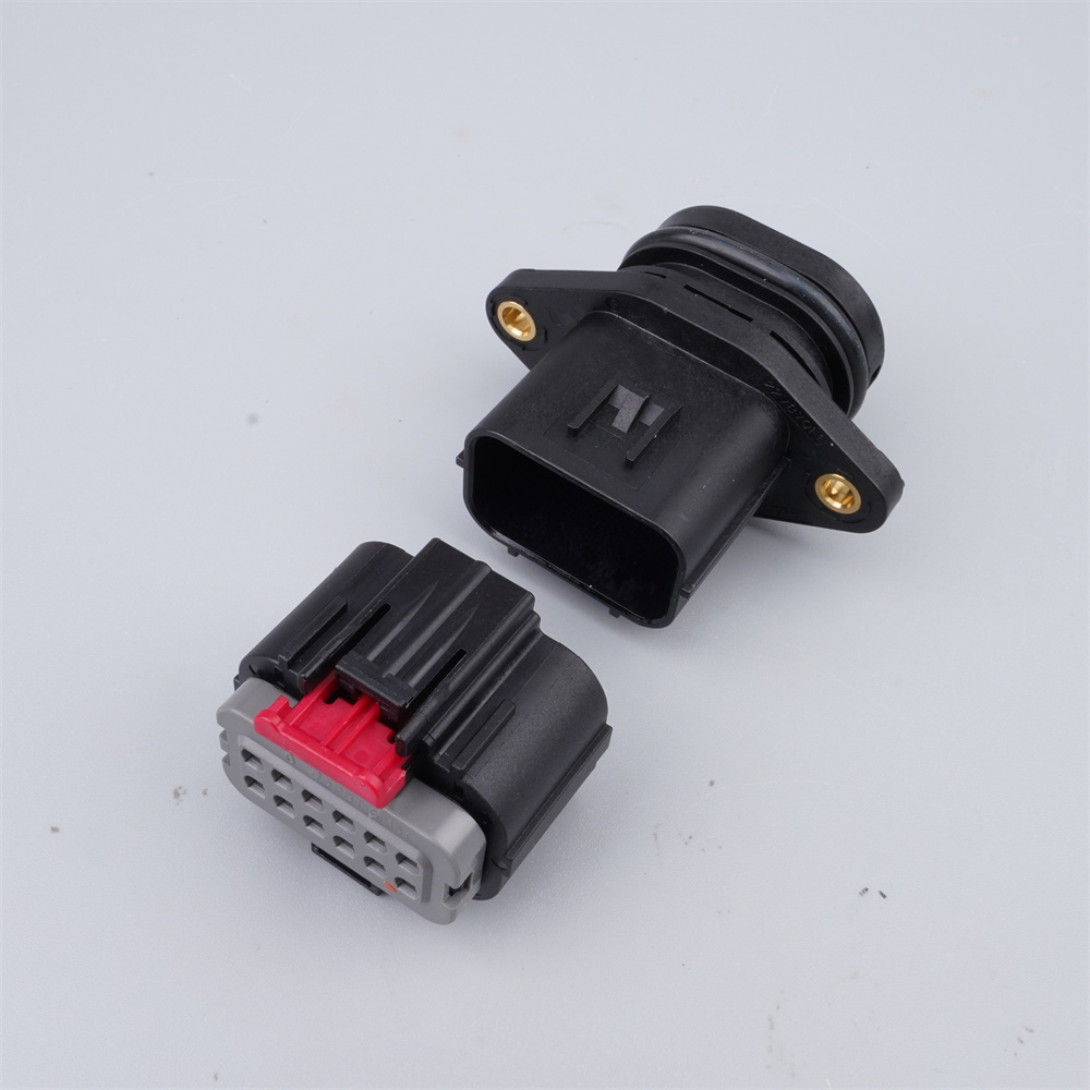
(1) Terminal BlocksTerminal blocks are primarily manufactured to facilitate easy wire connections. In practice, a terminal block consists of a metal strip enclosed in insulating plastic. Both ends of the metal strip feature holes for inserting wires, along with screws for tightening or loosening the connection. When it is necessary to connect two wires—or disconnect them—terminal blocks provide a convenient solution that allows quick disconnection without soldering or twisting wires together. There are many types of terminal blocks; common ones include plug-in terminal blocks, PCB terminal blocks, screw-type terminal blocks, and barrier-style terminal blocks.Features of terminal blocks: various pin pitches, flexible wiring methods, suitable for high-density wiring requirements; maximum current rating up to 520 A; compatible with SMT manufacturing processes; withstand reflow soldering temperatures up to 300°C; and functionality can be extended using various accessories.(2) Audio/Video Connectors① 2-pin and 3-pin plugs and sockets: primarily used for signal transmission between devices. The input plug often serves as a microphone input. 2-pin connectors are mainly used for mono signal connections, while 3-pin connectors are typically used for stereo signal connections. They are categorized by diameter into three standard sizes: 2.5 mm, 3.5 mm, and 6.5 mm.② RCA (Phono) connectors: commonly used in audio and video equipment for line-level input/output connections between devices.③ XLR connectors: primarily used for connecting microphones to amplifiers.④ 5-pin DIN sockets: mainly used for connecting cassette decks to amplifiers. They can consolidate both stereo input and output signals into a single connector.⑤ RCA plugs: primarily used for signal transmission.(3) Rectangular ConnectorsRectangular connectors consist of multiple contact pairs housed within a rectangular plastic shell with excellent insulation properties. The number of contact pairs varies and can reach dozens. Contacts may be arranged in two, three, four, or more rows. Good electrical contact is ensured by the normal force and friction generated from the elastic deformation of each contact pair. To enhance performance, some contacts are plated with gold or silver.Rectangular connectors can be classified as pin-type or hyperbolic spring-type; with or without an outer shell; and locking or non-locking types. These connectors are commonly used in low-frequency, low-voltage circuits, as well as mixed high- and low-frequency circuits, especially in radio communication instruments and test equipment.(4) Circular ConnectorsCircular connectors mainly fall into two categories: push-pull (plug-in) type and threaded (screw-type) connectors. Push-pull connectors are typically used in applications requiring frequent mating/unmating, with few contact points and currents below 1 A. Threaded connectors, commonly known as "aviation connectors," feature a standardized rotary locking mechanism. They offer convenient connection in multi-contact applications with high insertion/removal forces, excellent vibration resistance, and can easily meet special requirements such as waterproof sealing and electromagnetic shielding. They are suitable for high-current circuits where frequent plugging/unplugging is not required. These connectors range from 2 to nearly 100 contacts, with rated currents from 1 A up to several hundred amperes and operating voltages between 300 V and 500 V.(5) PCB ConnectorsPrinted circuit board (PCB) connectors evolved from rectangular connectors and technically belong to that category, though they are often listed separately as a distinct type. They feature anywhere from one to dozens of contacts and can be used either with ribbon cables or directly mounted onto circuit boards. They are widely employed in computers to connect various expansion cards to the motherboard. To ensure reliable connections, contacts are typically gold-plated—commonly referred to as "gold fingers."(6) Other ConnectorsOther types of connectors include IC sockets, power plugs and sockets, fiber optic connectors, and ribbon cable connectors.
-
Industry news
2025.10.09
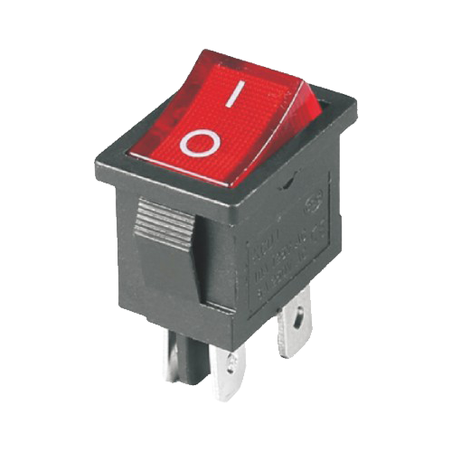
Stability of Rocker switch under power surge and electromagnetic interference (EMI)
Rocker switches play a critical role in modern power and electronic systems. Their applications span industrial equipment, household appliances, automotive electronics, and various power devices, requiring them to withstand diverse and demanding environmental and operational conditions. Under the influence of electrical surges and electromagnetic interference (EMI), the stability of rocker switches directly impacts the safety and reliability of the entire system. This article delves into key design considerations for rocker switches in mitigating electrical surges and EMI, analyzing how design strategies and material selection can enhance their stability to meet stringent requirements in power equipment, automotive electronics, and other applications.I. Causes of Electrical Surges and Surge Protection Design for Rocker Switches1. Causes and Hazards of Electrical SurgesElectrical surges refer to transient overvoltages occurring in power systems, typically caused by lightning strikes, motor startups, circuit breaker operations, or switching of other electrical equipment. These surges can be destructive to electronic components. When subjected to surges, rocker switches may suffer damage, overheating, or even fire due to excessive current or voltage. In industrial and automotive electronic systems, such sudden events not only disrupt equipment operation but also pose risks to user safety.2. Design Approaches for Surge Protection in Rocker SwitchesTo achieve effective surge protection, rocker switch designs should focus on the following aspects:Material Selection: Materials used in switches must exhibit excellent high-voltage and high-temperature resistance during surge events. Copper and silver alloys are commonly used as conductive materials due to their low contact resistance under high current. For housing materials, thermoplastic polymers and high-performance engineering plastics demonstrate superior heat and voltage resistance, effectively protecting internal structures from thermal damage.Contact Structure Optimization: Surge currents often cause contact erosion and wear, reducing contact reliability. Designing multi-point contact structures helps distribute current flow, reducing load on individual contact points and minimizing erosion risk. Additionally, silver- or gold-plated contacts further lower contact resistance and enhance durability.Integration of Protective Components: To improve surge tolerance, surge protection components such as metal oxide varistors (MOVs) or gas discharge tubes (GDTs) can be integrated within or around the switch circuitry. MOVs instantly absorb large amounts of energy during surges, clamping surge voltages to safe levels, while GDTs conduct under high transient voltages to protect the switch from damage. Such surge protection designs are particularly suitable for automotive electronics and power equipment.3. Application Example: Surge Protection Design in Automotive ElectronicsAutomotive electronic systems frequently experience surges during engine start-up or motor switching, imposing high demands on onboard rocker switches. For instance, rocker switches used in window controls or air conditioning systems require contacts capable of withstanding instantaneous high currents. One automotive manufacturer significantly reduced surge-related degradation by integrating MOVs and high-temperature-resistant alloy materials into their rocker switches, extending switch lifespan by over 20% while ensuring system stability and safety.II. Electromagnetic Interference (EMI) and Electromagnetic Compatibility (EMC): Impact and Optimization Strategies for Rocker Switches1. Causes and Challenges of Electromagnetic InterferenceElectromagnetic interference arises from external or internal electromagnetic signals that disrupt normal electronic device operation, including electrostatic discharge, radio-frequency interference, and power supply noise. For rocker switches in industrial equipment and power systems, EMI can cause switch malfunction, signal deviation, or even erroneous operation. Therefore, EMI/EMC optimization is crucial to ensure reliable performance of rocker switches in high-frequency and complex electromagnetic environments.2. EMI/EMC Optimization Strategies for Rocker SwitchesShielding Design: Adding internal metal shielding layers or incorporating conductive materials (e.g., carbon fiber or aluminum-coated materials) into the switch housing effectively blocks external EMI. These conductive materials absorb external electromagnetic waves and dissipate interference through grounding, ensuring stable electrical signal transmission.Integration of Filtering Components: Incorporating filtering capacitors or inductors into the switch circuit design reduces high-frequency noise interference. For example, RC filter circuits suppress high-frequency signals; by tuning capacitance and resistance values, they effectively eliminate high-frequency pulses generated during switch disconnection.Optimized Switch Layout and Grounding Design: Careful PCB layout and grounding arrangements minimize coupling between the switch and adjacent circuits. In industrial automation equipment, proper grounding and layout significantly reduce mutual inductance interference, thereby enhancing EMI immunity.3. Application Example: EMI/EMC Optimization in Industrial Automation EquipmentEMI/EMC issues are especially prominent in industrial automation equipment. One manufacturer addressed this by incorporating conductive plastics into the rocker switch housing and integrating filtering capacitors into the switch circuitry. This approach effectively reduced the impact of high-frequency interference on switch signals, improving equipment stability. Additionally, optimized grounding layouts minimized operational errors and signal deviations, meeting the high anti-interference demands of industrial applications.III. Future Trends in Stability Design for Rocker Switches1. Intelligent Adaptive Protection SystemsFuture rocker switch surge protection designs will increasingly adopt intelligent approaches. By embedding microcontroller units (MCUs) and smart sensors, rocker switches can monitor real-time current fluctuations and automatically disconnect circuits or activate protection modes upon detecting abnormal voltage or current, thereby enhancing surge resilience. For example, in smart power systems, real-time monitoring and adaptive switching not only protect the switch but also optimize overall energy efficiency.2. Application of Advanced and Composite MaterialsMaterial advancements will further expand rocker switch applications in extreme environments. Graphene offers exceptional conductivity and EMI resistance, while composite materials provide superior heat resistance and impact strength, making them promising candidates for next-generation surge- and interference-resistant designs. For instance, applying graphene-based materials to conductive pathways or using composites for housings could significantly enhance durability and EMI immunity.3. Integrated EMI/EMC SolutionsTo meet the demands of complex electromagnetic environments, future rocker switch designs will increasingly adopt integrated EMI/EMC solutions. Examples include rocker switches with built-in shielding and filtering functions, providing comprehensive interference protection within the switch itself and reducing the need for additional external circuitry. Such integrated solutions are particularly beneficial for industrial control systems, medical devices, and power systems with stringent EMI/EMC requirements.ConclusionTo address the challenges posed by electrical surges and electromagnetic interference, the stability design of rocker switches must integrate material selection, structural optimization, shielding techniques, and filtering measures. This ensures their reliability and durability in demanding applications such as power equipment, industrial automation, and automotive electronics. Looking ahead, continuous advancements in intelligent protection, novel materials, and integrated EMI/EMC solutions will further enhance the stability and adaptability of rocker switches, providing robust support for the safe and efficient operation of power and electronic systems.
-
Company news
2024.10.30
The website is under revamp
It's coming soon. Stay tuned!